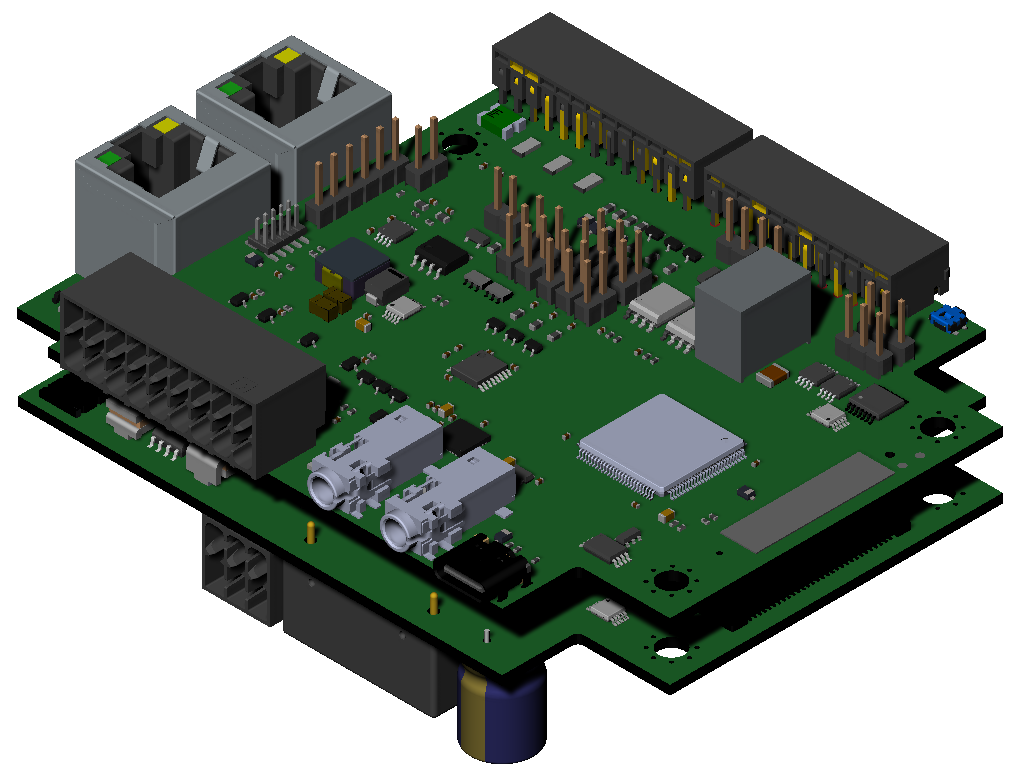
Multi Functional Control Board (MFCB)

This board has been developed to be used as a motor/rudder controlboard for drones / ROV's / ROTV's but can also be used in remote control stations to interface joysticks over ethernet towards a second MFCB which controls the vehicle remotely. In this way you are not limited to radio/wifi range but can also send the data over internet through a VPN connection.
It can controll any type of motor using one of the below control signals:
SBUS / PWM / CAN / RS232 / RS485 / Analog 0-10V / UART
For a minimum latency the board is equiped with Gigabit ethernet connections.
Specifications
Power input
- 2 x redundant 22-56V through power connector. On request the DC/DC converter can be replaced to support 9-36VDC** input range from a MOQ of 10 units and a lead time of 6-8 weeks
- PoE+ (802.3at)* input port
- USB-C power input port
*48-56V needed through either PoE input or DC
input connector in order to supply power through the PoE output port
** in case the DC/DC is replaced to support 9-36V the PoE+ input port will be
disconnected from the board to avoid to high power input on the DC/DC, meaning
that the board cannot be powered through PoE+ input port in this case, the PoE+
output will only work when there is 48-56V on the PoE+ input port
Power output
- PoE+ (802.3at) output port
- unregulated power =highest voltage of 3 DC inputs (PoE+ and the 2 DC input ports) fused with an automatic recovering fuse of 750mA
- 3 x 15V DC output port ) fused with an automatic recovering fuse of 125mA
- 3 x 5V DC output port fused with an automatic recovering fuse of 250mA
- 1 x 3.3V DC output port fused with an automatic recovering fuse of 1100mA
Communication ports
- 2 x RS232 port (Tx,RX & GND connections only)
- 1 x RS485 port
- 2 x CAN
- 2 x Gigabit ethernet (PoE+ in and PoE+out) through RJ45 connector
- 3 x 100Mbit LAN through SM04B-GHS-TB connector (for example to connect camera / ardupilot / radio's equipped with ethernet connection)
- Wifi Accespoint & client mode (simultaneous possible) through 2 x Ufl connectors
- Bluetooth (to be programmed)
- 3 x UART ports (of which 2 are jumper selectable for 3V3 or 5V output in order to support for example SBUS signals; all of them are 3V3/5V capable on their inputs)
- 1 x I²C port for external sensors
Peripheral ports
- 4 x 16bit high frequency analog input ports (0-10V)
- 2 x 16bit high frequency analog input ports (4-20mA)
- 4 x 16bit high frequency analog output ports (0-10V)
- 4 x PWM input ports
- 4 x PWM output ports (jumper selectable 3V3 or 5V output)
- 6 x GPIO ports for external relays or other purposes
- 2 Audio I/O*** (1 x line in / line out ; 1 x mic in, headphones out)
*** software drivers under devellopment
Processor
The board is foreseen of a 32 bit STM32H743 Arm®cortex®-M7 MPU. Additional RAM and storage memory can be added on request with a MOQ of 10 units and a lead time of 6-8 weeks.
Software
All basic
firmware is supplied to read and write all communication ports, to output data
on UDP and to read / write all peripheral ports. For the rest the board can be
programmed freely by the end user by the use of the language C++.
This gives you endless posibilities for configuration of the unit.
A Lantronics Xpico250 is foreseen for the wifi communication, this boards comes with a standard web interface. This unit is can be used to write your own webinterface fully independent of the functionality of the board making sure that the webinterface cannot cause any latency on the calculations done in the STM32 module.
For more information about the Xpico contact the lantronics website:
https://www.lantronix.com/products/xpico-250/#product-resources
Software can be written on request for your application, feel free to contact us for more info.
